Wednesday, November 1, 2023

Move over Numbnuts, We're taking this Industrial !

So, for a very little diorama I am working on, it's Z scale at 1:220 scale, I need a bit of forest litter for under some trees.  So I best make some, hadn't I.

So it was off to the side of the shed where Sarah up the road keeps a few native bee hives and I grabbed a few handfuls of dead leaves from whatever tree next door drops them there.  They were nice and dry and crunchy.


Out with my mortar and pestle and I ground them up into a fine powder and bits and pieces.


Then I got one of my really fine sieves I got from some kitchen section in the shops somewhere and sieved the results.  Came out quite well - bit of effort, but hey - pretty much free.  The remnants that were not needed were chucked into the garden as compost.


Old bottles and containers are always hoarded around here as they do come in handy.  Old spice jars are just the shot as they have the right sort of top to dispense the scatter.


So I poured a few sieves worth of scatter into them for use later.


Then I realised I needed a few different colours of scatter.  I needed a faster way - so now it was time to go Industrial on the job !

I went across the road to the footpath that has some Lilly Pilly and Paperbark trees growing on it.


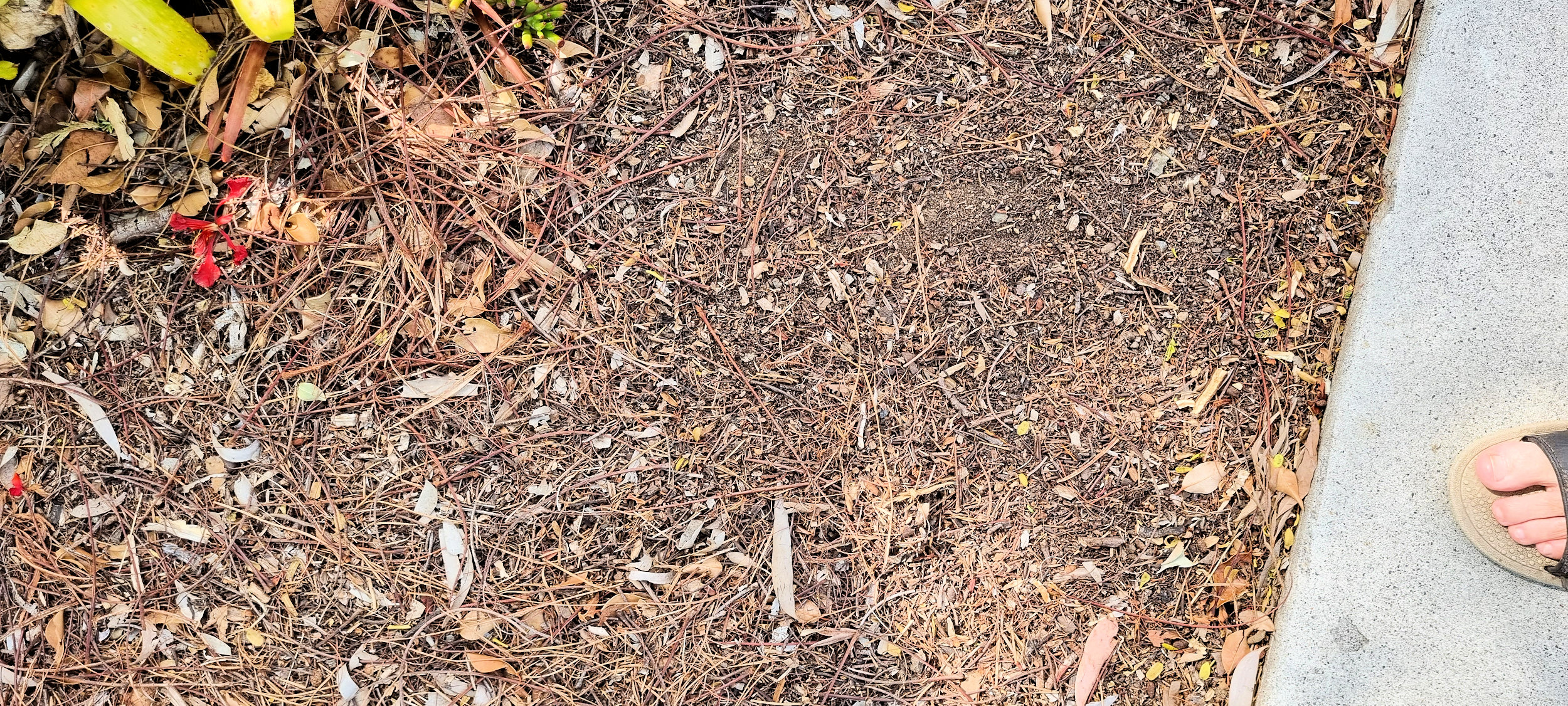
And under my Poinciana I grabbed a few handfuls of the compost I make from the leaves, twigs etc that drop down. 


So I brought it all in to my bench and got down to it.  


Now, being that Black & Decker are not too bad a brand of power tools, I of course had a nice chopper they make. Normally seen in the kitchen, mine has never see it - it has always been in the garage and used to make scatters :-)


Each material in turn was thrown in and ground up for a minute or two.


Then they were passed through the sieve.


And then placed into some plastic jars until needed a little later.  And the cost of course was nada.


PS. Normally I would put the makings into the oven at a very very low temp and cook for 5 minutes or so to kill off any bugs and their eggs.  Wouldn't want them hatching on your layout and crawling around, let alone eating parts of it.


Sunday, August 13, 2023

A Sunday Arvo Project

Setting up WiThrottle using my old Digitrax DB150 DCC system and a PR4


So, I am using “JMRI WiThrottle” software on a Raspberry Pi 3 B hardware base.  I even bought the cute official case for the Pi.


The OS I am using is the Raspberry Pi OS version 3.5.23

JMRI, and hence PanelPro, is version 5.4+R9005ecb4ac.

The DB150 has a 16 volt AV power supply (3 amps capable) as it’s power supply.  By the way, this is the same power supply I am using to power my NCE SB3 when it is connected up to this type of setup.


Output from the DB150 is connected to the tracks via my normal plug/socket method.  Hey, I bought a hundred from somewhere once – they’ll last me a looong time.


The 6 wire Data Cable is connected from the “A” port on the DB150 to the left hand port of the PR4.


The PR4 is powered by a 15 volt DC wall wart type power supply, which happens to also be what I power my SPROG II and my ESU Lokprogrammer with.  The PR4 is also sometimes connected direct to my PC so I can use JMRI to push sound files to Digitrax decoderes and program them.

And of course the Raspberry Pi is powered by a 5 volt DC wall wart type with 2 amp capacity.


So there is nothing much different in getting the Digitrax DB150 and PR4 going compared to the NCE SB3.  Plug it all together and once you have the JMRI software on the Pi, bring up the preference page and make sure that you set these settings under the “Connections” page:

“System Manufacturer” to “Digitrax”

“System Connection” to “LocoNet PR4”

“Serial Port” to “ttyACM0”

“Connection Prefix” to “L” – auto sets anyway.

“Connection Name” to “LocoNet” – auto sets anyway.

And that pretty much is all I needed to do.  The Raspberry Pi has been set to connect into my normal WiFi at home, so I then connect my phone into that network and can then play with Engine Driver on the phone and drive my trains on the test track.  So now I can use either my NCE SB3 or this old Digitrax DB150 to test drive large trains and consists via WiThrottle.


Sunday, July 2, 2023

I Need MORE Power Scotty !

OK, so I got out the old DCC system, the NCE SB3 Smart Booster, I have sitting in a dusty box.  I've not had to use it in ernest as I have not needed more power to the rails than the NCE PowerCab or the SPROG II puts out (about an Amp each).  Hey, I've only been programming or testing single locos or at most a couple of N scale ones in a consist.  But this little beauty, the SB3 puts out up to 3 Amps of power - yeeehaaarrr.


The SB3 on the left and the power supply on the right.

Well, I now want to do up some big consists - 6 or 7 (Tim the Toolman is grunting in the background, so maybe more...) locos.

Now, I also managed to find the old NCE USB Interface I bought years ago and haven't used in yonks since I got the SPROG II years ago.


USB Interface with USB cable at the top heading off to the PC and 
the data cable at the bottom heading off to the SB3.

So, for test running a few big consists, I have cleared all the crap off of the test track and cleaned it up again.  Now I need to work out and setup WiThrottle so I can drive the trains with my phone - much easier than buggerising around with the NCE Hammerhead (PowerCab).  Mind you, I have never setup WiThrottle before either - how hard can it be?

So a quick gander at the JMRI website of the instructions - yeh, yeh, I know what I'm doing.. hehehehe - ever heard those famous words before?

Funny enough, It wasn't that hard.  I got my USB Interface, plugged in the correct flat NCE 6 pin RJ12 Cable, Plugged in the USB cable into the USB Interface and then into the PC. Plugged the other end of the RJ12 cable into the SB3, Connected the power to the SB3 and then the output from it to the Tracks.

I of course already had JMRI installed on the PC - been using it for years - what a great piece of software for model train nuts.

And next I did this:

Made sure the PC was running on the 2G WiFi network at home and NOT the 5G one, as the phone is ancient and only uses the 2G WiFi.

Next were these steps:

1. Start JMRI on the PC

2. Edit Connections when the error pops up (steps 3-7)

3. Select System Manufacturer of NCE

4. Select System Connection of NCE USB

5. Select Serial Port of COM5

6. Select System of PowerCab

7. Select USB Version of V7.x.x

8. Actions

     Start Web Server

9. Actions

     Start WiThrottle Server

10. Fire up the Phone and Start up the Engine Driver application and connect to the Discovered Server.


The PowerCab is only to show how big they are compared to the phone behind it.  
Might be an old phone, but does the job.  Mind you, the PowerCab gets a bit of use
as a quick testing tool since it is all in one.

11. As the little furry animal says - Simples.  I played trains.  I'll tidy up the cabling and make a little box or something to make it all neat... later.

Now where are the rest of those SD70 MAC's so I can get them all running at the same speed for a good consist? .....


Tuesday, May 30, 2023

Whadjacallit - Powerpack, Stay Alive, Current Keeper...

OK, since last time, I've whacked a few more of these super capacitor based thingamebobs into my HOn3½ QR locos - the 2400 class this time.  These have the same chassis and mech as the 1550's and 2100 classes as well.  So my previous knowledge, or lack thereof, is of use.


After doing a 2100 for a mate from the club using my patented and pending box kite method, see my last blog post, 


See, it looks like a box kite - I reckon so any way.


The box kite installs into the mechs' tower.

I was about to add one of these stay alives into a 2400 class of mine when it hit me - like a low hanging beam under a Queenslander, boom! Sometimes you can't see it even when it is inches from your face - beams about to hit you and locations to install things...

Of all things, I was so engrossed in the centre of the loco where the decoder was, the motor etc, that I didn't look at the farrrr end.  Yep, the front end.  In the loco shell, just above the coupler box and in front of the drivers cab, there is this space - looks small.  But it's not small, it's juuuust right.  Just right for an ESU single cell Powerpack, or Stay Alive, or Current Keeper, or whatever you want to call these little battery type gizzmos.


So that's where this last one has been shoe horned. Lots less hassle and work :-)   I did of course attach a small three pin set of plugs to the Stay Alive and Decoder so that it is not permanently connected to the decoder - just in case of future work on the decoder.

I only needed a tiny bit of double sided tape to hold the stay alive in place and then to keep the wires tidy, I used a small drop of Glue that is set with a bit of UV light.


A small drop on the cab base holds the three wires in place (above). And then another small drop half way to the decoder (see below) keeps it tidy and makes putting the shell back on a bit easier.


So that's eleven QR's in the fleet done - one more and I have a carton done.

Oh, and I reckon if you wanted MORE, I hear Tim the Toolman in the background, you could squeeze a home made stay alive in there with one cell in the front, two in the area where I did the box kite and depending on the decoder used, one next to the decoder...  4 cells works nicely, but just make sure for big programming jobs to disconnect your homemade jobbie from the decoder while programming - stops possible damage since there is no ESU circuit in place (comes with their own brand stay alives).

Now this loco will smoothly charge over points and dirty spots here and there :-)

Monday, May 15, 2023

Ah, ha, ha, ha, Stayin' Alive, Stayin' Alive


Whether you're a brother or whether you're a mother

You're stayin' alive, stayin' alive

Feel the city breakin' and everybody shakin'

And we're stayin' alive, stayin' alive

Ah, ha, ha, ha, stayin' alive, stayin' alive

Ah, ha, ha, ha, stayin' alive


Ah, ha, ha, the Bee Gees. Anywho, since I was looking at how to install a Stay Alive in a 2100 class QR loco for a friend, he's decided we'll do the install on Saturday before the NMRA meeting up the road.  Crikey, I better get prepared ASAP!

So I already have a new ESU Stay Alive on hand, so he can give me his and I'll give him mine - see photo above.  It is of course an ESU PowerPack Mini 54671.  

So I thought about the four ways I came up with on how to install one in the 2100 loco (see last blog entry) and decided the box kite method will be the jobbie.  While I was at it, I thought I'd open up my 1550 class QR loco made by that Wuiske mob, as the Stay Alive I put in it a year or two back has stopped working and since they are the same mech as the 2100, I could get prepared for the weekend as well as fix a problem if I had one.

Well, bugger me dead if I hadn't accidently cut a wire from the Stay Alive to the Decoder when I had assembled the loco last time I had it apart - had put a screw right through a wire and severed it - dead as an XPT on a mates layout - kaput.

So I soldered on a new wire and got it ready to put back in the box kite I had made last time.

Now that I had the old box kite out, OK, it's not a kite but sort of looks like one.  It is some 5 and 10 thou styrene sheet glued together to sit in the tower on the loco mech and hold the Stay Alive bits in place and stop them falling down into the mech itself.  Below is a pic of the old one with the Stay Alive's super capacitor in place.

And these 2 shots show the new one being built in preparation for installation in my mates loco this weekend.


Next we plonk the box kite in position to make sure it fits.  Looks good to me.  No glue will be needed.

Now. Now we modify the Stay Alive a tad.  My last one as you saw above had wires between the Stay Alive's circuit board and its super capacitor.  This time I just cut the heat shrink off and bent the super capacitor out by 180 degrees and wrapped some kapton tape around it for electrical protection.

The next shot shows the Stay Alive bent into position.

Here it is with kapton tape on it and ready to go flying - Ah, ha, ha, ha, stayin' alive, stayin' alive.


And here we see a test fit of the Stay Alive in the box kite in the mech's tower. Looks like it will do the job nicely.


For future ease of maintenance I also soldered on a small three wire plug to the Stay Alive so it can be disconnected from the Decoder whenever needed.  See below.


Now to wait till Saturday and all that will be needed is to open up the loco and solder the matching 3 pin plug to the Decoder and test her out.


Saturday, May 13, 2023

I'll Keep You Alive


A fellow QR modeller asked me the other day about fitting a Stay Alive (or Keep Alive - what's in a name) in a Wuiske brand of QR 2100 loco, in HO scale.

So some research with my loco was in order and then eventually I decided to progress and whack a Stay Alive in my QR 2100 loco.  My plan is to have all my QR locos with stay alives to cater for dirty track and poor trackwork that you sometimes come across on some layouts...  Not that my wheels would EVER be dirty... no, never...  ;-)

Step one was to rip the loco's shell off - carefully. Crikey that bench of mine is getting messy again!  QR locos are so narrow and not too tall either - not much room I'm afraid.  And this loco has two parts of sweet FA space to play with.


Above you see the shell off, but when it sits on the mech, there's not much space free in there.

I proceeded to see where I could plonk a Stay Alive.  It turned out there's no room for a home made one, be it a five or a four cell version.  So I got the measurements for the ESU single cell Stay Alive - they call it a PowerPack, from the ESU website via a google search (careful what you search for...) and I proceeded to see if it would fit.  Bugger - nothing suitable without cutting or grinding the mech.

Don't know what made me look, but I did and found that the google search had given me the OLD measurements for the OLD version of the ESU PowerPack.  So with the new dimensions now on hand for the ESU 54671 PowerPack I recompared the spaces.  Here is the little Stay Alive itself.  There is a circuit board that does circuit type stuff with the electricity and there is a single super capacitor soldered to it.  It is 15.7 mm x 9.7 mm x 13 mm in size.


I found four possible sites or ways to install the Stay Alive - only one needed any filing or cutting.


The above photo shows the Stay Alive sitting in the mech tower.  It is a smidge too big on the circuit board so would not fit down low enough.  But I reckon a small amount of filing or grinding of the tower would allow it to fit nicely.


The above shot shows the rear end of the shell with the decoder, an ESU Micro, double sided taped to the inner roof. This space is suitable. You see, the yellow box I drew, well the decoder and Stay Alive will fit within that and will be below the height limit posed by the shell mounting post - pointed to by the red arrow.  This will be the method I use.


Another option I reckon is to use the mech tower, but modify the Stay Alive.  I haven't modified it in the above shot, but the yellow outline shows where the circuit board would be.  You see, the super capacitor part of the Stay Alive will fit in the tower. Now if we were to cut the heat shrink off the device and bend the circuit board 180 degrees out, it would sit in the space on the left of the tower - voila.

In the above shot you can see the Stay Alive on its side and on an angle sitting between the mech tower and the decoder plug area.  You just need to make sure it doesn't cover the screw hole that the loco shell uses.  Maybe even a piece of sheet styrene to make a plate for it to sit on and keep it from dropping down into the mech.


So I proceeded with installing the Stay Alive in the same area as the  decoder.  Now as per the photo above, this is the area above the loco I have to play with.  The yellow circle marks where I must stay clear to allow the shell screw to come through.


First up we need to solder the three wires from the Stay Alive to the Decoder.  I had to cut a bit of heat shrink carefully off of the Decoder first to expose the three solder pads where the wires will go.  Two pads are currently unused - easy peasy.  The one on the other side though, is used as the common for the circuit.  So there is already a wire soldered there - see the first of the two shots above.  


So careful careful when I solder.


The above two shots show that I needed to add some double sided tape to the Decoder and Stay Alive so I could position them in the shell so they wouldn't get out of position when the shell is put back on.


Above, we can see them now in place - noice one PK, I says to meself.


Above, the shell is loosely in place so I can test the loco to make sure that (1) she still works and that (2) the Stay Alive works.  I fired her up and all was good with the work :-)  She moves and also goes toot toot, and even does it for a few seconds when lifted off the track now.


Above, she is all screwed together and ready to run.

I won't talk about the 15 minutes or so poking around positioning wires and swearing a lot to get it all fitted in.  Maybe a hot glue drop here and there next time to hold wires out of the way might be the go :-)